Visual examination of concrete structures
Visual examination consists of the observation of visible defects on the surface of a structural element with a view to locating and classifying defects. It is a non-invasive examination and can provide insight into areas that may require more detailed investigation.
The examination is normally carried out by experienced personnel who use sketches and photographs to record the defects, along with direct measures of their location and extent using tapes, rulers, crack width gauges or other small equipment.
It is the most widely used inspection system and is generally reported using a formal inspection report.
A systematic approach must be used to ensure total coverage, starting at one point in the structure and moving periodically through all elements.
What do I need to carry out a visual examination of a concrete structure?
Equipment used for visual examinations normally used includes:
camera.
binoculars.
flashlight.
clipboard and paper (or field book or formal inspection form).
tape measure (15 to 30 m).
graduated ruler (1 mm).
crack gauge.
depth gauge.
knife.
hammer (1 kg).
Visual examination can be carried out without the need for special access but the value of an inspection can be reduced where elements cannot be approached, e.g., high bridges, low-clearance bridges and culverts, inside box girders, etc. If a comprehensive visual examination is required (e.g., for a Principle Inspection), it is necessary to approach all surfaces to within touching distance.
Access to some parts of the structure may require specialized equipment, such as:
ladders,
scaffolding,
truck mounted platforms,
abseiling equipment,
boats,
diving apparatus,
confined space equipment.
Drones
No visual survey should be undertaken without a risk assessment developed in the planning stage.
What should I look for during a visual inspection?
The objective of a visual survey is to identify and quantify any visible defects in the structure for further investigation.
Each defect will indicate a specific set of deterioration mechanisms that could be at fault. Testing will then be employed in the next stage of the survey to ascertain which of these mechanisms is in fact the root cause of the damage and quantify how bad the problem is.
How do I identify important defects and what do they mean?
The tables below summarize the defects commonly found during visual examinations, how to identify them and the deterioration mechanism that may have caused them.
Mechanisms marked with a * take place at a specific stage of concrete production such as during the casting and curing of the concrete (Shrinkage cracks, thermal cracks, honeycombing etc). Although the effects these defects have on the structure may intensify or fade with time, the process that created them has ceased.
Defect | Deterioration mechanisms |
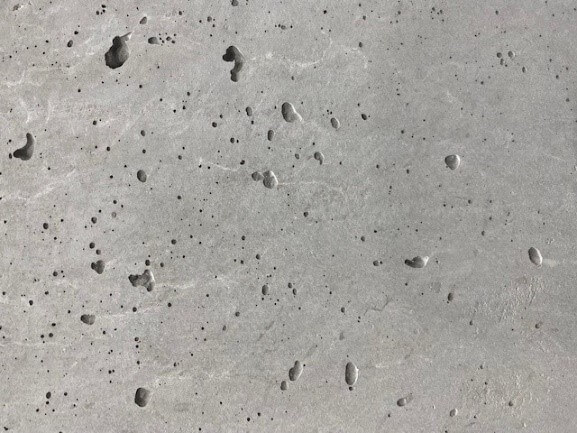
Bugholes | Under vibration |
Excessive concrete viscocity | |
Evidence: | |
 | |
Defect | Deterioration mechanisms |
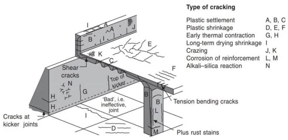
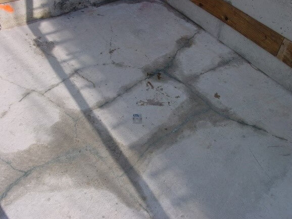
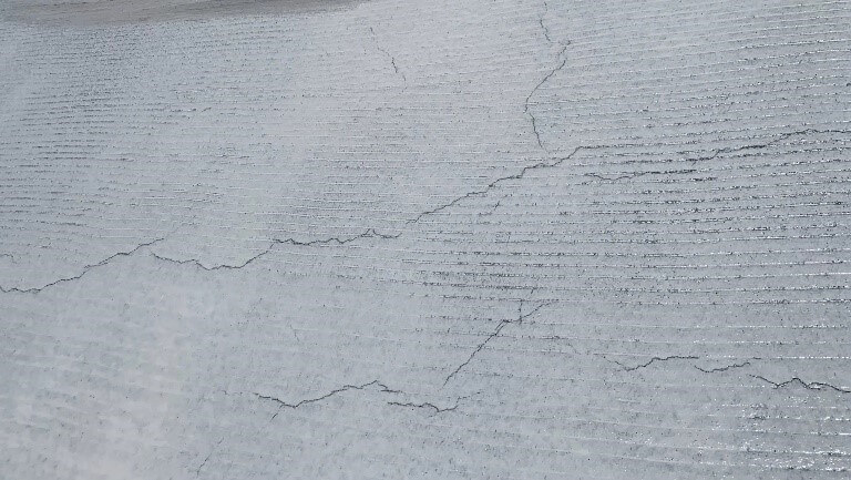
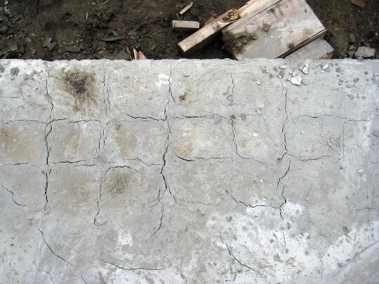
Early age cracks | Thermal cracking* |
Shrinkage* | |
Evidence: | |
Crack identification
Thermal cracking
Shrinkage cracking
| |
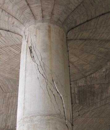
Defect | Deterioration mechanisms |
Structural cracks | Fatigue |
Overloading | |
Evidence: | |
| |
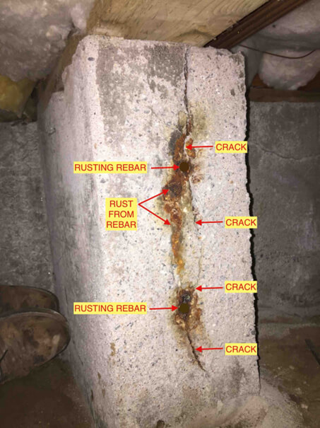
Defect | Deterioration mechanisms |
Corrosion cracking | Reinforcement corrosion |
Evidence | |
 | |
Defect | Deterioration mechanisms |
Expansive cracking | Alkali Aggregate Reaction (AAR) |
Internal sulphate attack (ISA) | |
Freeze / thaw | |
Evidence: | |
ISA AAR
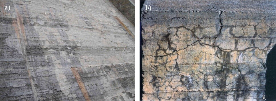
Freeze / thaw 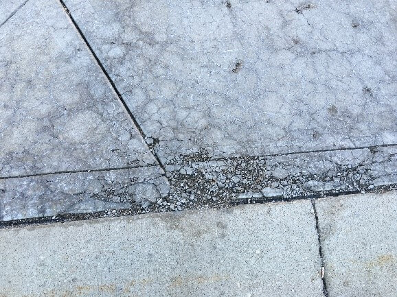 | |
Defect | Deterioration mechanisms |
Deflection | Alkali Aggregate Reaction (AAR) |
Internal sulphate attack (ISA) | |
Creep | |
Evidence: | |
AAR Internal sulphate attack (ISA) 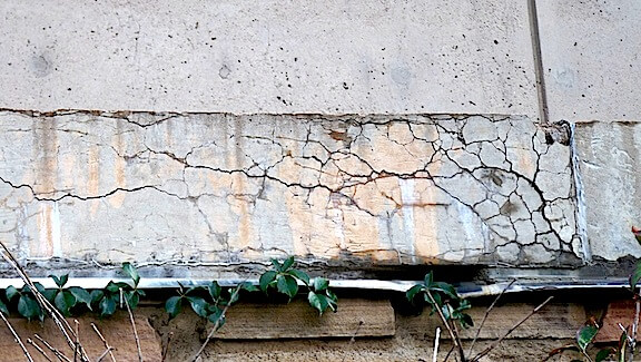 Creep 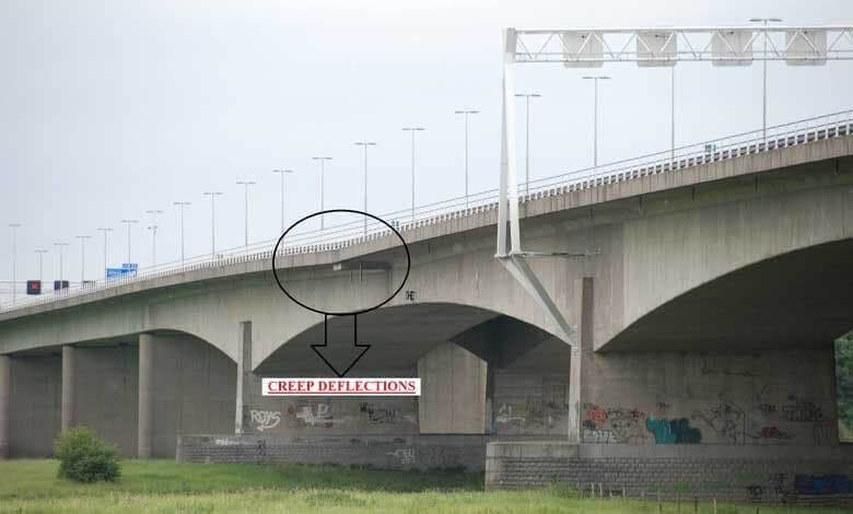 | |
Defect | Deterioration mechanisms |
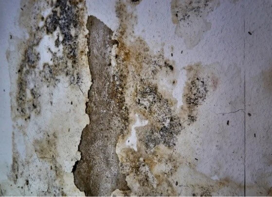
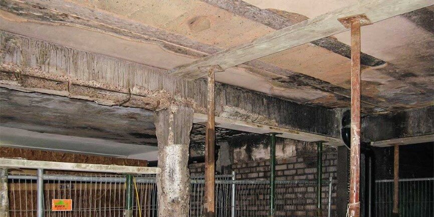
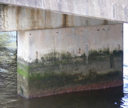
Discoloration | Acid attack |
Biological deterioration | |
Alkali Aggregate Reaction (AAR) | |
Internal sulphate attack (ISA) | |
Fire | |
Evidence: | |
Acid attack
Biological deterioration
Alkali Aggregate Reaction (AAR) 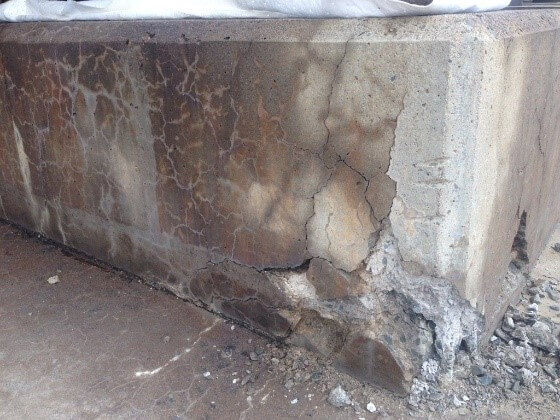 Internal sulphate attack (ISA) Fire | |
Defect | Deterioration mechanisms |
Efflorescence | Leaching |
Alkali Aggregate Reaction (AAR) | |
Internal sulphate attack (ISA) | |
Evidence: | |
Leaching 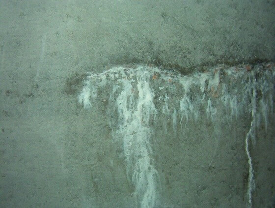 Alkali Aggregate Reaction (AAR) 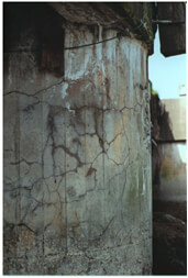 Internal Sulphate Attack (ISA)  | |
Defect | Deterioration mechanisms |
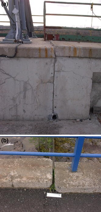
Elemental translation or rotation | Alkali Aggregate Reaction (AAR) |
Internal sulphate attack (ISA) | |
Creep | |
Evidence: | |
AAR ISA Creep | |
| Defect | Deterioration mechanisms |
| Eroded concrete | Acid attack |
| Abrasion / erosion | |
Evidence: | |
Acid attack 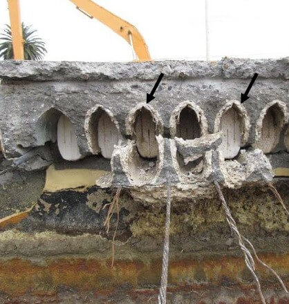 Abrasion / erosion 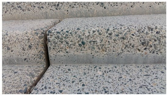 | |
Defect | Deterioration mechanisms |
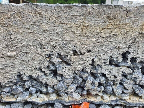
Honeycombing | Inadequate compaction* |
Excessive reinforcement density* | |
Evidence: | |
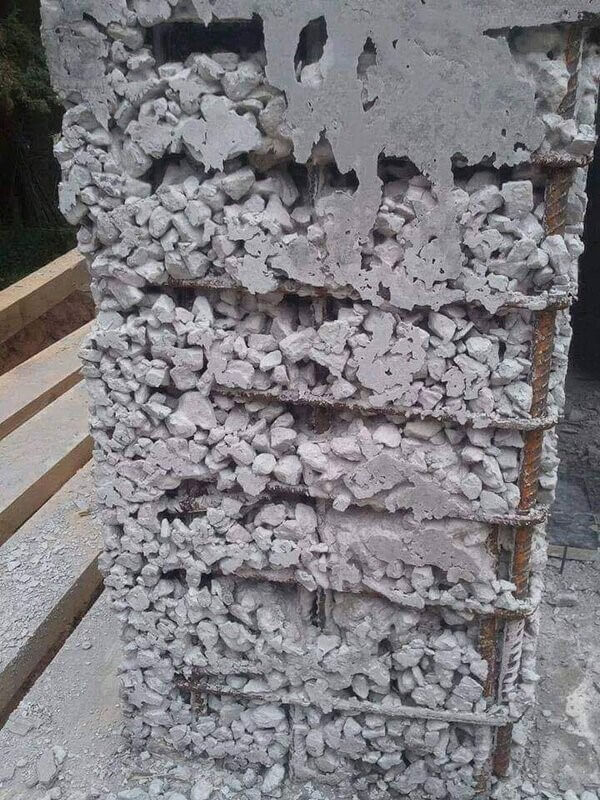 | |
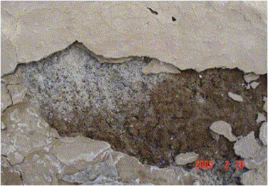
| Defect | Deterioration mechanisms |
| Inorganic, organic and biological contamination | Biological deterioration |
Evidence: | |
 | |
Defect | Deterioration mechanisms |
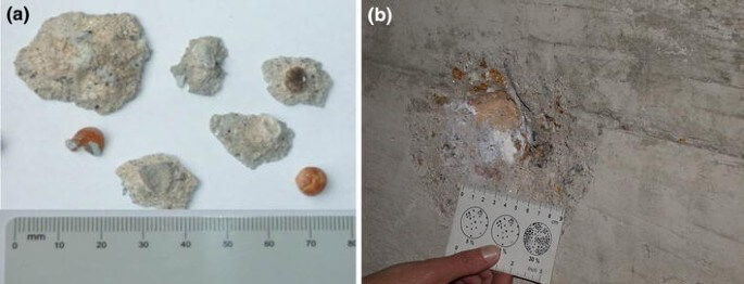
Pop outs | Alkali Aggregate Reaction (AAR) |
Freeze / thaw | |
Fire | |
Evidence: | |
AAR
Freeze/Thaw 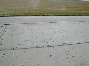 Fire 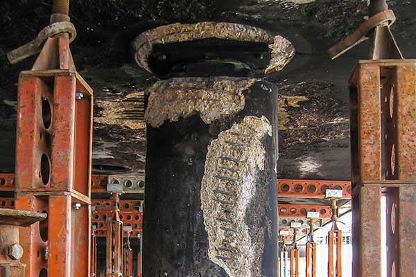 | |
Defect | Deterioration mechanisms |
Scaling | Acid attack |
Alkali Aggregate Reaction (AAR) | |
External sulphate attack (ESA) | |
Freeze / thaw | |
Abrasion / erosion | |
Evidence: | |
Acid attack 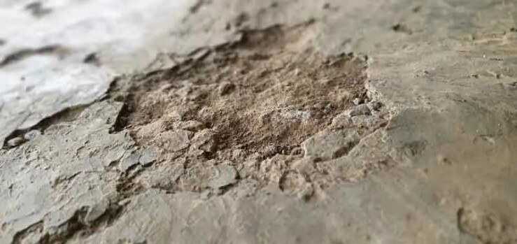 AAR 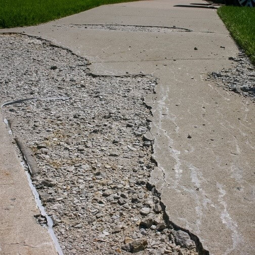 ESA 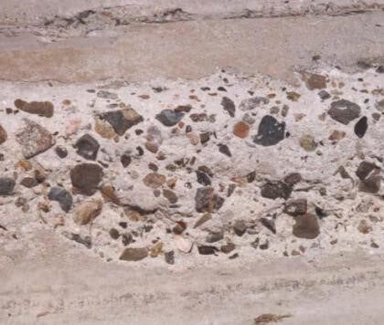 Freeze / Thaw 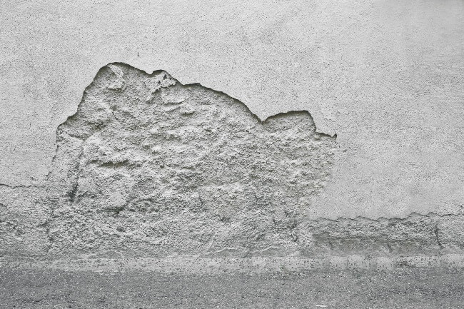 | |
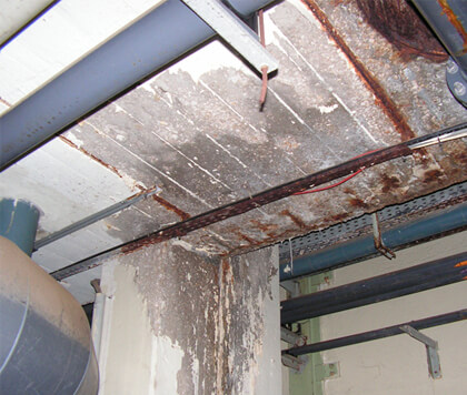
Defect | Deterioration mechanisms |
Spalling | Reinforcement corrosion |
Chloride contamination | |
Carbonation | |
Evidence: | |
Reinforcement corrosion 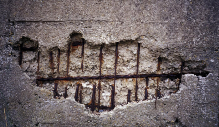 Chloride contamination 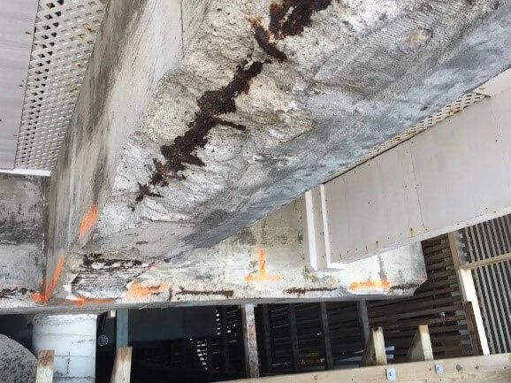 Carbonation 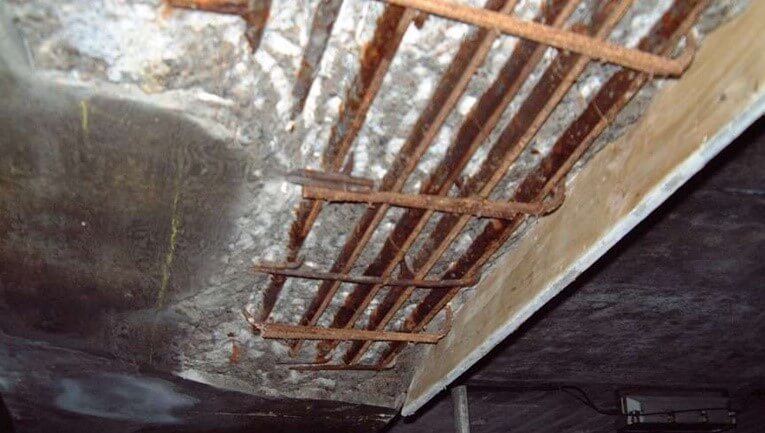 | |
Defect | Deterioration mechanisms |
Steel fracture | Alkali Aggregate Reaction (AAR) |
Reinforcement corrosion | |
Evidence: | |
AAR 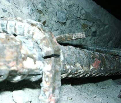 Reinforcement corrosion 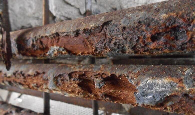 | |
Defect | Deterioration mechanisms |
Steel loss | Reinforcement corrosion |
Chloride contamination | |
Carbonation | |
Evidence: | |
Reinforcement corrosion 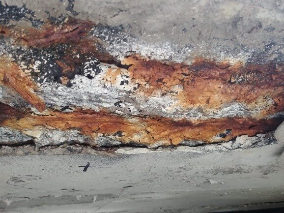 Chloride contamination 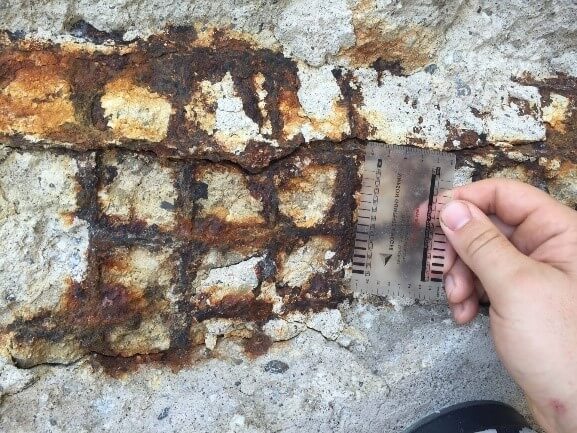 Carbonation 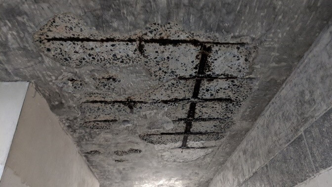 | |