What is Electrical resistivity testing of concrete?
Electrical resistivity testing evaluates concretes resistance to the flow of electrical current and as a result assesses the chloride ion penetration resistance of concrete elements and the corrosion risk of its reinforcement.
The test involves applying a current between two points on the concrete's surface and measuring the potential difference, offering insights into the material's porosity and moisture content. This technique is crucial for predicting the service life of concrete structures and ensuring their long-term integrity and safety.
Resistivity is correlated with transport properties, which makes the information useful for all deterioration processes involving water or transport of aggressive agents.

How does Electrical resistivity testing work?
The resistivity of cement paste, mortar and concrete depends on the pore volume and pore-size distribution of the cement paste, the pore-water composition and the moisture content of the concrete.
The resistivity of concrete exposed to chlorides gives information about the risk of early corrosion damage, because generally a low concrete resistivity is correlated to more rapid chloride contamination. Resistivity mapping may show the most porous spots, where chloride contamination is likely to be fastest and future corrosion rates will be highest.

Surface resistivity testing of concrete, employing a four-probe Wenner electrode array (Figure 1), is the most commonly used, on site test to evaluate electrical resistivity of concrete. The four electrodes are evenly spaced with the internal electrodes emitting current into the concrete and the central electrodes measuring the electric potential.
What is Electrical resistivity testing used for?
Deterioration process | Defects | Control of repairs |
Heterogeneity in concrete |
How do I carry out Electrical resistivity testing?
A simple step by step procedure based on RILEM TC 154-EMC and AASHTO T 358 is presented below:
Ensure the concrete surface is free from dust, loose particles, or any coatings to ensure accurate measurements and good contact between the probes and the concrete, reducing the risk of erroneous readings.
Determine electrode spacings. These typically range from 38.1mm to 50mm depending on aggregate size to ensure adequate penetration depth and limit the influence or surface conditions or adjacent reinforcing bars.

- Position the Wenner array on the concrete surface. Probes are typically not physically attached but held against the surface and conductive gel may be used to ensure good electrical contact and stability.

Apply current and measure the potential difference in voltage between the external and central probes. Currents are typically in the microampere to milliampere range, selected to minimize the risk of electrolysis while still ensuring sufficient signal strength for accurate measurements.
Calculate the resistivity (ρ) in Ω/m from the electrode spacing (a) in meters, the voltage (V) in volts, and the current applied (I) in amperes using Formula 1.
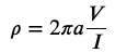
Formula 1. Wenner four-pin method formula for calculating electrical resistivity.
Lower resistivity indicates higher chloride ion permeability, suggesting a greater risk of corrosion for embedded steel. Figure 3 illustrates the relationship between this test, chloride penetration resistance and corrosion risk.

Test data is often used to create models or graphs for detailed analysis, aiding in structural health monitoring and maintenance planning. Professionals often employ resistivity contour maps or 3D visualization models to pinpoint areas of potential corrosion risk within concrete structures.
What equipment and expertise are required for Electrical resistivity testing?
For surface electrical resistivity testing of concrete, essential equipment includes Wenner probe devices like the Proceq Resipod which is handheld, easily portable and comes with ResipodLink to create resistivity contour maps or 3D visualization models for detailed analysis, aiding in structural health monitoring and maintenance planning. to create resistivity contour maps or 3D visualization models for detailed analysis. Electrical resistivity tomography can be used to enable easy identification of defective areas or even small cracks that may not be visible to the naked eye.
Expertise required involves understanding of concrete properties, familiarity with the testing standards and ability to interpret resistivity values in the context of concrete durability and chloride penetration resistance. Proper training ensures accurate setup, testing, and data interpretation.
What are the advantages of Electrical resistivity testing?
Measures concrete's electrical resistivity accurately, providing insights into durability and corrosion potential.
Results can indicate permeability to chloride ingress in an easier way.
Quick, cheap and easy to perform, offering real-time results.
Leaves no mark so suitable for repeated monitoring.
Facilitates early detection of potential corrosion issues.
Can be used as a quality control measure during concrete curing.
Helps in the assessment of concrete mix designs for future projects.
Electrical resistance tomography can reveal cracks that cannot be identified during visual inspection.

What are the disadvantages Electrical resistivity testing?
Accuracy may be influenced by external conditions such as temperature and humidity.
Requires clean, exposed concrete surface for effective testing.
Equipment cost might be prohibitive for small-scale projects.
Requires skilled operators for accurate data interpretation.

How accurate is Electrical resistivity testing?
Surface resistivity testing devices can identify changes in resistance with an accuracy between ±0.2 to ±2 kΩ/cm dependant on the resistance of the material measured, however, even with optimal procedures and equipment considerable scatter is present in most sets of resistivity measurements. Variation in results for tests carried out on the same concrete, in the same conditions, can be expected to vary by as much as 10 or 20%, with 30% variation not uncommon for field measurements.
Figure 4 illustrates the environmental and internal factors that can affect the electrical resistivity of concrete and therefore the predicted durability and maintenance requirements.
What are the limits of Electrical resistivity testing?
Environmental and site-specific conditions, including variations in moisture levels and temperature, can significantly impact measurements.
Complementary analyses, such as determining the concrete's total and free chloride content, assessing carbonation depth, and measuring corrosion rates, are essential for a comprehensive condition assessment.
Calibration of testing equipment is crucial for quantitative evaluations, ensuring that readings accurately reflect the concrete's condition.
The inherent heterogeneity of concrete can lead to discrepancies in resistivity measurements, underscoring the importance of considering multiple data points.
Ancillary information
Maturity of test: > 10 years
Qualification & interpretation : Inspector and specialist
Service disruption: No
Preliminary works: Yes
Time consumption Medium (one day)
Cost Low
Access to element 1 face
References and further information